2.9.4.DISSOLUTION TEST FORTRANSDERMAL PATCHES
This test is used to determine the dissolution rate of the activeingredients of transdermal patches.
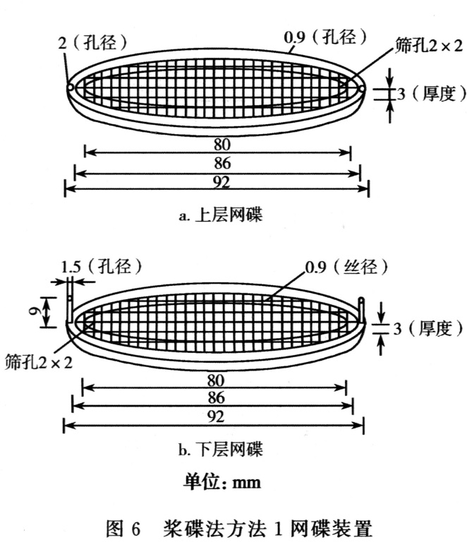
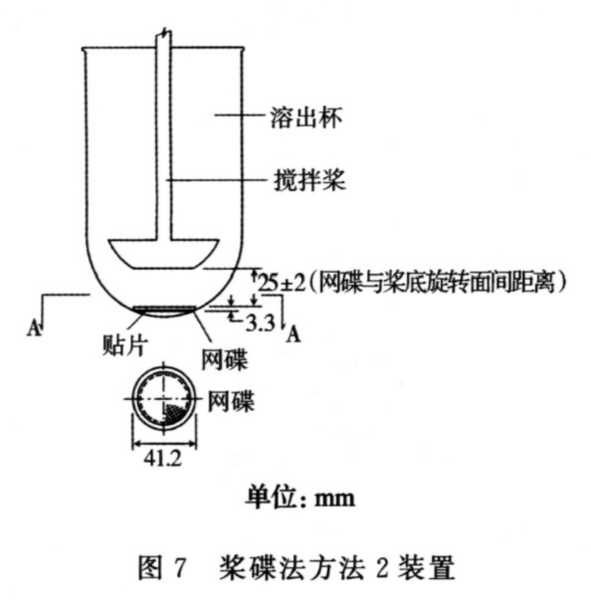
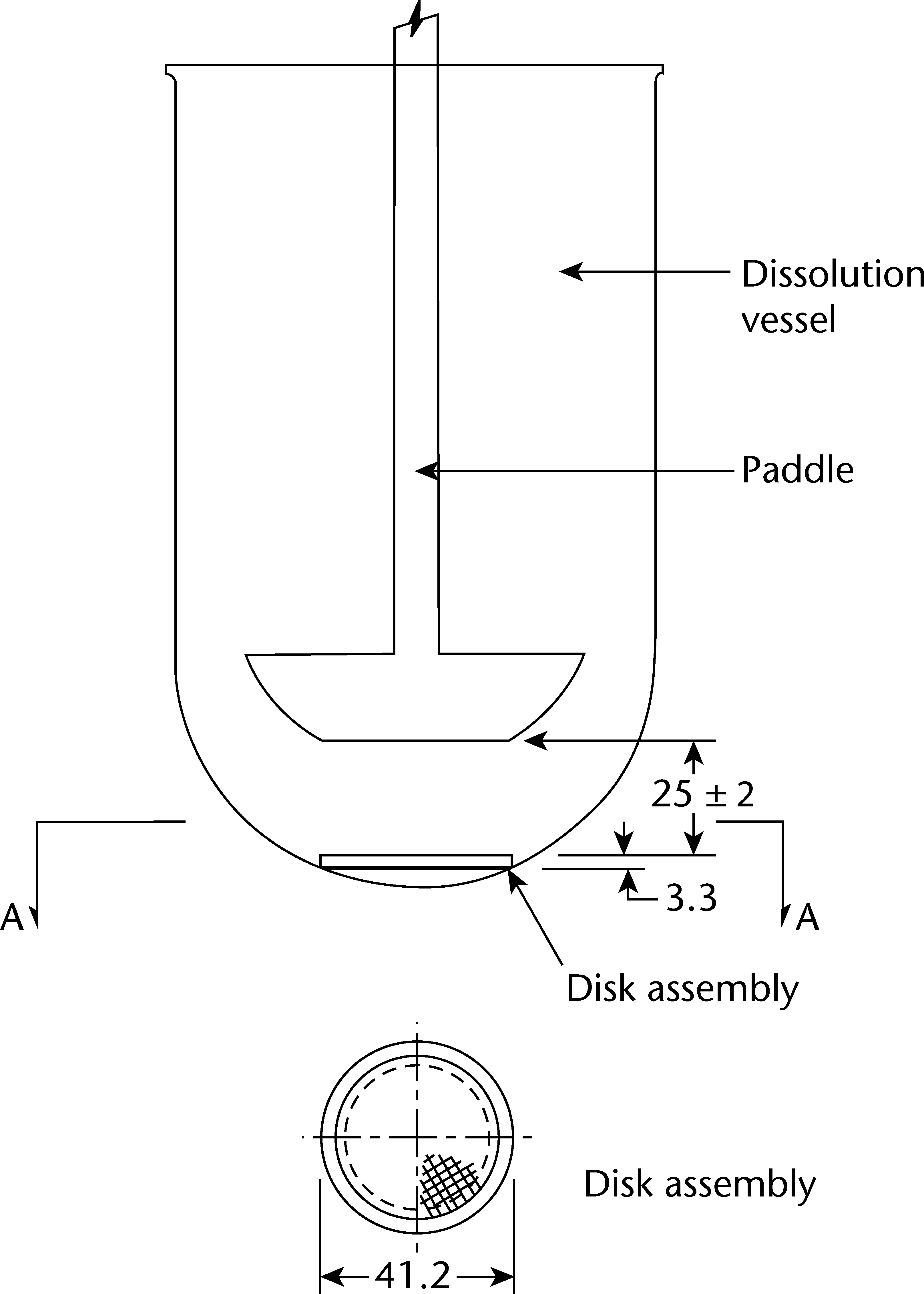
1.DISK ASSEMBLY METHOD
Equipment. Use the paddle and vessel assembly from thepaddle apparatus described in the dissolution test for solidoral dosage forms (2.9.3) with the addition of a stainless steeldisk assembly (SSDA) in the form of a net with an aperture of125 um (see Figure 2.9.4.-1).

The SSDA holds the system at the bottom of the vessel and isdesigned to minimise any dead volume between the SSDA andthe bottom of the vessel. The SSDA holds the patch flat, withthe release surface uppermost and parallel to the bottom of thepaddle blade. A distance of 25 + 2 mm between the bottom ofthe paddle blade and the surface of the SSDA is maintainedduring the test (see Figure 2.9.4.-2). The temperature ismaintained at 32 + 0.5 C. The vessel may be covered duringthe test to minimise evaporation.
 Procedure. Place the prescribed volume of the dissolutionmedium in the vessel and equilibrate the medium to theprescribed temperature. Apply the patch to the SSDA,ensuring that the release surface of the patch is as flat aspossible. The patch may be attached to the SSDA by aprescribed adhesive or by a strip of a double-sided adhesivetape. The adhesive or tape are previously tested for the absenceof interference with the assay and of adsorption of the activeingredient(s). Press the patch, release surface facing up, ontothe side of the SSDA made adhesive. The applied patch mustnot overlap the borders of the SSDA. For this purpose andprovided that the preparation is homogeneous and uniformlyspread on the outer covering, an appropriate and exactlymeasured piece of the patch may be cut and used for testingthe dissolution rate. This procedure may also be necessaryto achieve appropriate sink conditions. This procedure mustnot be applied to membrane-type patches. Place the patchmounted on the SSDA flat at the bottom of the vessel withthe release surface facing upwards. Immediately rotate thepaddle at 100 r/min, for example. At predetermined intervals,withdraw a sample from the zone midway between the surfaceof the dissolution medium and the top of the blade, not lessthan 1 cm from the vessel wall.Perform the assay on each sample, correcting for any volumelosses, as necessary. Repeat the test with additional patches.
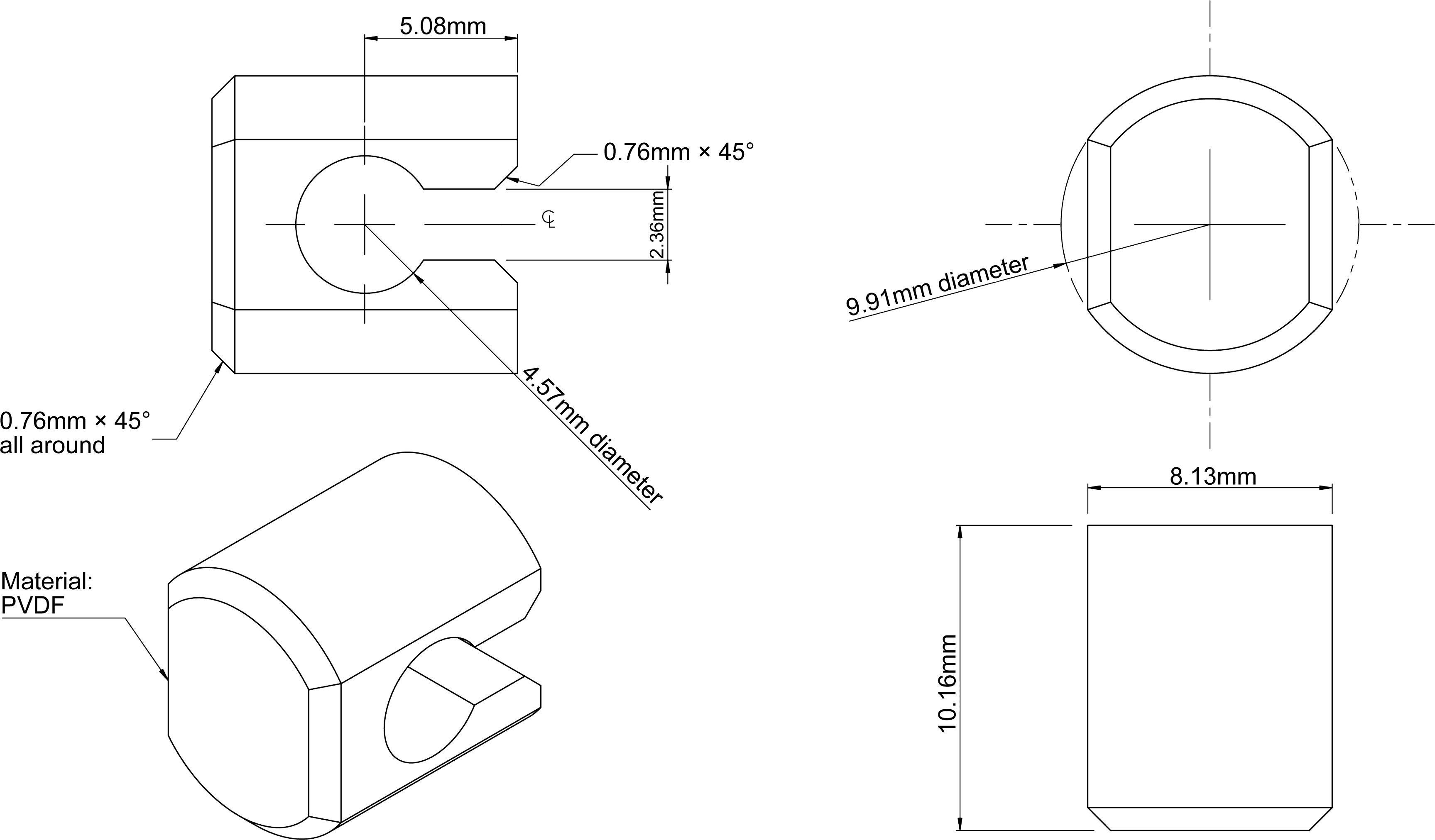
2.CELL METHOD
Equipment. Use the paddle and vessel assembly from thepaddle apparatus described in the dissolution test for solidoral dosage forms (2.9.3) with the addition of the extractioncell (cell).
The cell is made of chemically inert materials and consists ofa support, a cover and, if necessary, a membrane placed onthe patch to isolate it from the medium that may modify oradversely affect the physico-chemical properties of the patch(see Figure 2.9.4.-3).
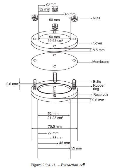
Support. The central part of the support forms a cavityintended to hold the patch. The cavity has a depth of 2.6 mmand a diameter that is appropriate to the size of the patch to be examined. The following diameters can be used: 27 mm,38 mm, 45 mm, 52 mm, corresponding to volumes of 1.48 mL,2.94 mL, 4.13 mL, 5.52 mL, respectively.Cover. The cover has a central opening with a diameterselected according to the size of the patch to be examined.The patch can thus be precisely centred, and its releasingsurface limited. The following diameters may be used: 20 mm,32 mm, 40 mm, 50 mm corresponding to areas of 3.14 cm”,8.03 cm?, 12.56 cm, 19.63 cm?, respectively. The cover isheld in place by nuts screwed onto bolts projecting from thesupport. The cover is sealed to the support by a rubber ringset on the reservoir.
Extraction cell. The cell holds the patch flat, with the releasesurface uppermost and parallel to the bottom of the paddleblade. A distance of 25 + 2 mm is maintained between thepaddle blade and the surface ofthe patch (see Figure 2.9.4.-4).The temperature is maintained at 32 + 0.5 ·C. The vessel maybe covered during the test to minimise evaporation.Procedure. Place the prescribed volume of the dissolutionmedium in the vessel and equilibrate the medium to theprescribed temperature. Precisely centre the patch in thecell with the releasing surface uppermost. Close the cell, ifnecessary applying a hydrophobic substance (for example,petrolatum) to the flat surfaces to ensure the seal, and ensurethat the patch stays in place. Introduce the cell flat intothe bottom of the vessel with the cover facing upwards.Immediately rotate the paddle, at 100 r/min for example. Atpredetermined intervals, withdraw a sample from the zonemidway between the surface of the dissolution medium andthe top of the paddle blade, not less than cm from the vesselwall.
Perform the assay on each sample, correcting for any volumelosses, as necessary. Repeat the test with additional patches.